BLOW MOLDING SIMULATION
Processors have tried to visualize what happens inside a blow mold during the blow process for many years. With the advent of Finite Element Analysis and ever-faster Personal Computers, it has now become possible to simulate this event at a reasonable cost and good accuracy.
I have tested a program called "B-Sim". It has been available for about a year and is one of few commercial packages on the market at the moment. The lay-out of this description is such that sections that refer only to stretch blow molding are in blue while sections for extrusion blow molding are in green.
First let's look at the components that you will need to run a simulation:
The preform data
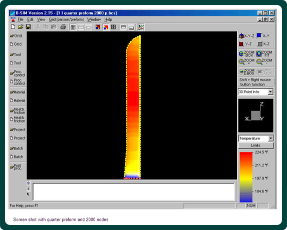
The user creates a preform manually by inputting wall thickness and temperature data into a simple text file. The user also specifies the number of data points (nodes) to create the parison. A higher number means longer computing time but better resolution. To cut down on computing time, a quarter parison can be created for round bottle shapes or a half parison for oval shapes. This reduces the number of nodes to a quarter or half what would be needed for a round preform without any loss of accuracy. 2000 nodes for a quarter preform yield good resolution in the final bottle shape. Furthermore, critical sections of the preform can be refined in a very simple process for higher accuracy. Temperature data needs to be gathered with an infrared temperature sensor on an existing preform. The test points should start right underneath the support ledge and increase in 5 mm increments. Temperature will vary between 95º C and 115ºC (203º F and 239º F) and can be adjusted in either process. In the two-stage process temperature control is more precise and can be varied to a greater extent whereas in the single-stage process the adjustments made affect the whole preform during the injection stage.
Once finished, the user imports the created text file into B-Sim and it creates a visual representation of both thickness and temperature
BLOW MOLDING SIMULATION
 The parison data
Parisons are created in a simple process where the diameter and temperature is specified. The rules for the number of nodes is the same as with preforms above. It is possible to ovalize the parison in several ways. There is also an add-on module that programs devices such as PWDS and outputs data for it and the programmer directly to the machine controls.
The mold and stretch rod data
The stretch rod is easily created by using an existing design that is
BLOW MOLDING SIMULATION
is supplied with B-Sim and changing the diameter to suit. Mold data is somewhat more difficult as the software will work best with data in the "STL" format, used mostly by mold makers. "DXF" files out of AutoCAD did not show properly and needed to be converted by one of the high-end CAD packages. The best approach is to get the mold data from the mold maker if bottle data in this format are not available. Up to ten individual tools can be entered and moved at any time during the cycle. Moving mold inserts of any shape can be simulated and optimized.
The material data
B-Sim provides general data sets for a variety of resins. However, the material you are using might not totally conform to these sets. Both material manufacturers and independent labs provide a set of data for about US$2,000. Before you spend the money, check with the provider what type of machinery they are using. Only high-end lab equipment will be able to simulate the rapid expansion of the PET during the blow molding process. Inferior machines will stress the material at rates that are only 1/10th of the actual rates and then extrapolate the data, with questionable results.
The process data
Here is where the software truly shines. In a simple interface, any process condition that can be imagined is easily applied and changes can be made with just a few keystrokes. Angular data from the rotary blow molders must be converted into time intervals, which is easy enough.
The only challenge one faces here is to know how quickly the blow pressure actually enters the preform or parison. I would recommend to mount a pressure transducer on one of the air lines as close as possible to the neck of the bottle and, using the start signal for pressure 1 and 2 respectively as reference, monitor how long it takes before the pressure is fully recorded by the sensor. These values are then entered into B-Sim and the first set of solutions can be run. Mold closing speeds should also be recorded first on an actual machine to get real world data into the program.
BLOW MOLDING SIMULATION
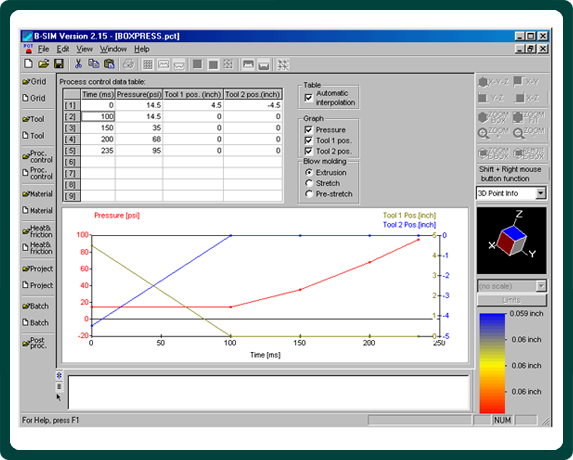
Process data screen with pressure and mold movements
Other data
Finally you enter material specific conductivity and chiller water temperature data on your molds as well as friction factors and you are ready to run your first simulation.
I do recommend running a simulation with an existing product first. This will calibrate the software to the particular processing conditions of the blow molder. Possible adjustments you might have to make come from time delays between the blow air valves and the blow cavities,
BLOW MOLDING SIMULATION
material data and preform or parison temperature variations. Once 80% of your data points are within 0.004" (0.1 mm) of the actual wall thickness of the bottle in question, you can start working on that project you acquired the software for.
Simulations
The hardware you will need is a Pentium 2 or 3 computer with 128 MB of RAM. Expect the simulations to take between 5 minutes and 1 hour depending on your computer and the complexity of the part. Batch processing is available so you will spend most of your time analyzing the part rather than waiting for the simulation to finish.
Post processing
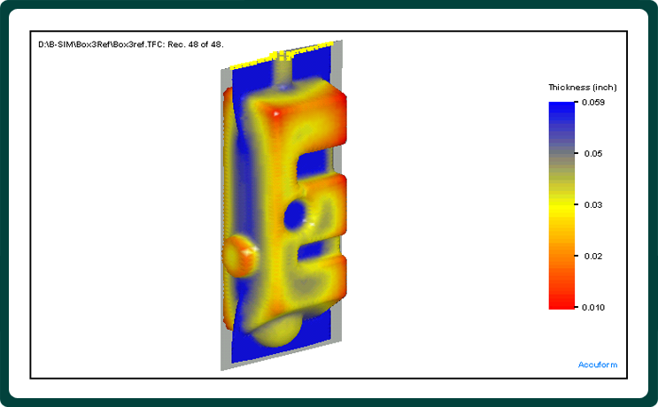
Once the simulation has finished you simply click the post-processing button to start your analysis. B-Sim can display temperature, wall thickness or stress in a color scheme that is adjustable to your needs. A cut-window allows you to cut through the container in any plane and view a graph displaying the wall thickness. You can then easily export these numbers to a spreadsheet and compare them there to the product requirements.
BLOW MOLDING SIMULATION
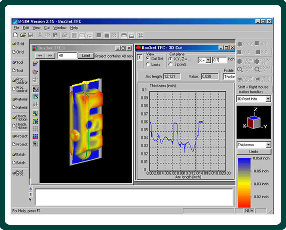
Wall thickness graph and cut plane; the line on the right guides the cross hair on the left
Applications
The first application that comes to mind is of course the preform design. While it is not possible to predict the final wall thickness to the last 0.001", the program shows good correlation between moving material in the preform and the corresponding results in the bottle. Several preform designs can be tested in a single day by using the batch-processing feature. Use preform temperatures between 100º C (212º F) and 110º C (230º F) for CSD bottles for the simulations keeping in mind that thicker preform sections keep heat better than thinner ones,
BLOW MOLDING SIMULATION
Head tooling development for large, industrial applications is another area for quick pay-backs. Not only is head tooling expensive, even more money is spent by tying up expensive machinery with weeks of product development. Once the mold data is available (usually weeks before the mold delivery)
BLOW MOLDING SIMULATION
the user can start to develop the proper size head tooling, experiment with different ovalization patterns or find an initial program for PWDS or similar devices. The next version of the software will allow the independent movement of up to ten different tool sections, thus allowing the simulation of moving mold inserts.
Another application is to evaluate bottle base designs for optimal design and processing conditions. This evaluation should not only include wall thickness distribution but also the encapsulation of stress in the base. Higher stress increases the propensity to stress cracking especially in the summer under hot and humid conditions.
You could also analyze different stretch rod designs and their effects on the base and general wall thickness distribution.
B-Sim is also an incredible training tool for processors. The user can adjust timing and amount of pressure or variations in the stretch rod speed and watch the effect on the bottle. Unfortunately, not every processor gets to go to the machine manufacturer for training and there are few training programs available so that most of the training is done in-house. With simulation software, training is available 24 hours/day and you can design custom programs that truly reflect the conditions in your plant.
Conclusion
Blow molding simulation software is no magical solution to design and processing problems. But it adds a tool to our repertoire that allows us to do development work before the molds are being manufactured and without tying up multi-million $ machinery. Ever-closer packaging specifications and shorter time to market deadlines will bring many mold makers and processors to this new technology.


 The experts at Apex Container Tech Inc. are here to assist you in your current business or with starting a new one